Before you start
GRE tunnelling technology was added in NSX 6.4. This technology has minimal functionality: IPSec and OSPF services do not recognize GRE interfaces and there is no logging or monitoring implementation except for simple ping. Currently, GRE tunnels can only be created by NSX administrators via the REST API. VCloud users cannot use this feature.
However, VMware has implemented the creation of encrypted tunnels via Route-Based IPSec VPN (VTI over IPSec). This technology is identical to Generic Routing Encapsulation (GRE) over IPSec, except that no additional encapsulation is added to the packet before IPSec processing is applied. The table below shows which vendors support this feature. The difference from normal GRE lies in the encapsulation method: VTI saves 4 bytes by eliminating the GRE header..
| Vendor | Route-Based IPSec VPN support |
|---|---|
| Cisco | yes |
| Juniper | yes |
| Mikrotik | no |
Introduction
The original problem's goal is to achieve fault tolerance under the scheme when two encrypted tunnels are created from a remote OFFICE on the same channel to two Edges (EDGE-2 and EDGE-3) which are located in different data centers but connected by an L2 line. You can see the scheme below.
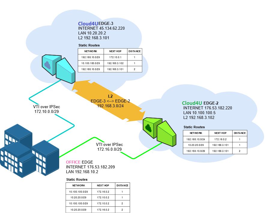
We need to configure the infrastructure so that in the event of a loss of connection between the OFFICE and one of the EDGE devices is lost, the availability of the infrastructure in subnets 10.20.20.0/29 and 10.100.100.0/29 can be maintained. To achieve this, follow these steps:
- Deploy the infrastructure in each VDC (networks, vApp and VM).
- Create Route-Based IPSec VPN tunnels between OFFICE-EDGE-2 and OFFICE-EDGE-3 nodes.
- On the EDGE-2 and EDGE-3 nodes, create static routes to OFFICE via GRE.
- On the OFFICE node, create static routes to EDGE-2 and EDGE-3.
- Test the created infrastructure for availability.
- Ensure the availability of all nodes in the scheme by turning off one of the tunnels.
For ease of identification, all screenshots of the nodes will be colour-coded according to the following key::
OFFICE - 45.134.62.220
EDGE-2 - 176.53.182.220
EDGE-3 - 176.53.182.209
This article on EDGE covers the Office node, but you can configure any supported device to implement this scheme.
To reduce the amount of information, duplication of screenshots from the same nodes has been minimised.
Preparing the infrastructure
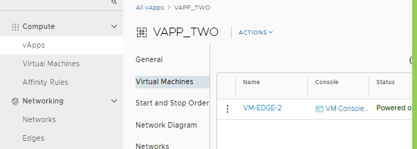
- Create a vApp (VAPP_TWO) and a VM (VM-EDGE-2) in the VDC. Do the same for the other nodes.
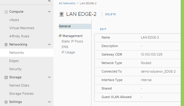
Create an EDGE-2 LAN 10.100.100.0/29 and connect it to EDGE-2. Do the same for EDGE-3 (LAN-EDGE-3 10.20.20.0/29) and for Office (192.168.10.0/29)
- Go to EDGE>VPN>IPSec settings and choose to create IPsec VPN Sites
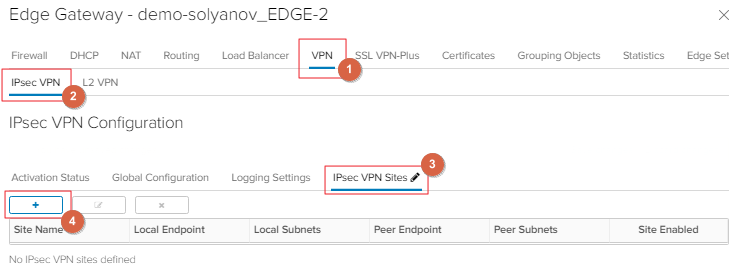
- Create Route-Based IPSec according to the matrix of all three nodes (on the Office side you must configure two tunnels, one to each EDGE node):
| Parameter | EDGE-3 | EDGE-2 | OFFICE |
| Name | TO Office |
To Office |
To EDGE-1, To EDGE-2 |
| Local ID | 176.53.182.220 | 45.134.62.220 | 176.53.182.209 |
| Peer Subnets | 0.0.0.0/0 | 0.0.0.0/0 | 0.0.0.0/0 |
| Encryption Algorithm | AES-256 | AES-256 | AES-256 |
| Peer Subnets | 0.0.0.0/0 | 0.0.0.0/0 | 0.0.0.0/0 |
| Encryption Algorithm | AES-256 | AES-256 | AES-256 |
| Authentication | PSK | PSK | PSK |
| Pre-Shared Key | *** | *** | *** |
| Diffie-Hellman Group | DH14 | DH14 | DH14 |
| Digest Algorithm | SHA-256 | SHA-256 | SHA-256 |
| IKE Option | iKEv-2 | iKEv-2 | iKEv-2 |
| Session Type | Route-Based Session | Route-Based Session | Route-Based Session |
| Tunnel Interface IP CIDR | 172.16.0.2/30 | 172.10.0.2/30 | 172.16.0.1/30, 172.10.0.1/30 |
| Tunnel Interface MTU | 1500 | 1500 | 1500 |
- Configure static routes between the created tunnels on each node.
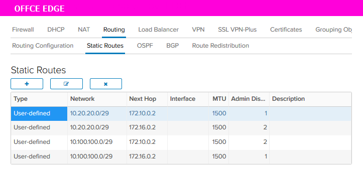
| SOURCE | NETWORK | NEXT HOP | DISTANCE |
|---|---|---|---|
| EDGE-3 to EDGE-2 (L2) | 10.100.100.0/29 | 192.168.3.102 | 1 |
| EDGE-3 to Office (VTI) | 192.168.10.0/29 | 172.10.0.1 | 1 |
| EDGE-3 to Office через EDGE-2 |
192.168.10.0/29 |
192.168.3.102 |
2 |
| EDGE-2 to EDGE-3 (L2) | 10.20.20.0/29 | 192.168.3.101 | 1 |
| EDGE-2 to Office (VTI) | 192.168.10.0/29 | 172.16.0.1 | 1 |
| EDGE-2 to Office через EDGE-3 |
192.168.10.0/29 |
192.168.3.101 |
2 |
When creating the static routes, specify the subnet behind the opposite node in the Network field. In the 'Next Hop' field, enter the IP address of the opposite node's IPSec tunnel.
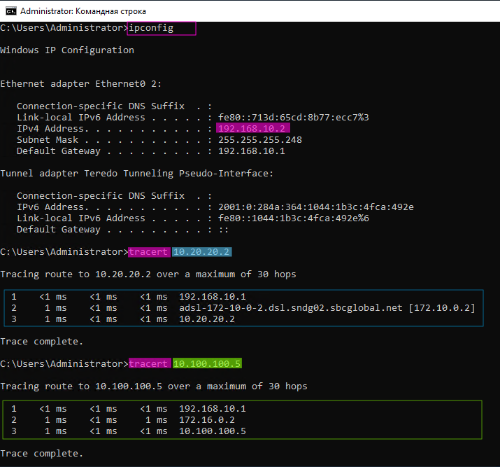
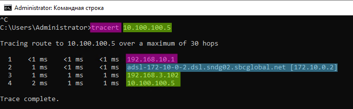
- From the Office node, record the availability of subnets connected to EDGE-2 and EDGE-3
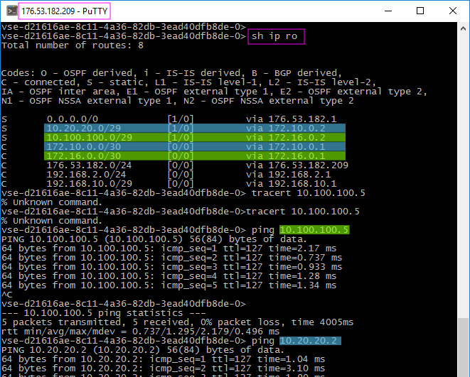
- Use the created tunnels to fix the traffic to subnets.
Checking availability after disconnecting the tunnel.
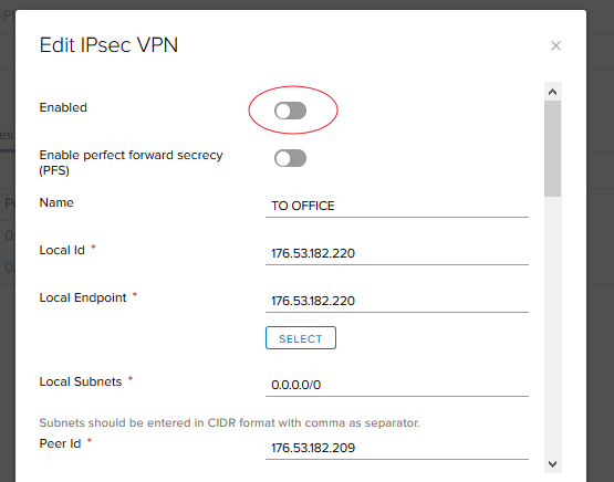
- With all the hosts connected, we need to disable the tunnel on the Office > EDGE-2 (172.16.0.0/30) route. This will allow us to verify that the route to the subnet behind EDGE-2 goes through EDGE-3. To achieve this, the IPSec VTI tunnel on the EDGE-2 host must be disabled.
2. Note that the EDGE-2 subnet remains accessible via a route through the EDGE-3 node.
- Similarly, check the availability of Office on EDGE-2
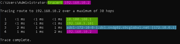
As you can see, the node is still available, so the fault tolerance is fixed.
